Input and Output files in STA tool
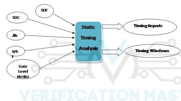
SDF (Standard Delay Format)
SDF file is used for Fetching and Analyzing the timing data at any stage of the design process. The data in SDF file is in ASCII format and it is independent of the tool being used. It contains the below Design related information :-
- Timing Constraints
- Path Delays
- Interconnect Delays
- Port Delays
SDC (Synopsys Design Constraints)
SDC file is used to define the various constraints of an ASIC like Operating Frequency, Power Constraints, and Area. Different EDA tools use SDC for the analysis and synthesis of a Design. The SDC file is written in Tool Command Language (Tcl).
.lib (Liberty File)
In .lib file contains cell delays, capacitance value, transition time setup, and hold time. Liberty files can be characterized based on two models; these are NLDM and CCS models. CCS model is more accurate compared to the NLDM model as there are more simulation points in the CCS model and in NLDM mode there are fewer simulation points. So basically in .lib, information related to time, voltage, leakage power, input and output threshold, and output load is present.
SPEF (Standard Parasitic Extraction Format)
SPEF file contains information related to parasitic components of a design like Resistance and Capacitance values. This file is in ASCII format and is automatically generated by a tool.
Gate Level Netlist
It is the file that is generated by the Synthesis tool and is given as input at various stages of the complete ASIC flow. Gate level Netlist contains the information of the logical connectivity between all the Standard cells and Macros.
Difference between .sdf and .lib
.sdf file contains the timing information of the chip implementation at any stage whereas .lib are generated by the characterization of standard cells. It doesn’t contain the timing information of chip implementation but contains only timing information of standard cells. An SDF file of one stage can be used as an input for timing calculation and optimization at the next stage.
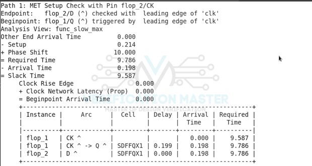
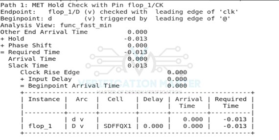
Timing Report (Report_Timing)
Timing Reports Contains the following Information
- Beginpoint: From where Timing Path starts
- Endpoint: The point at which Timing Path ends
- Analysis View: Whether a Design is working in a specific condition or not (Mode of Operation + PVT Corner + RC Corner)
- Required Time: The time at which the Data is Required to be present at a Pin
- Arrival Time: The time at which the Data Arrives at the Pin
- Slack: Difference between the Required Time and Arrival Time
- Latency: Time taken by a Clock Signal in travelling from its Source to Sink
- Instance Names: Names of Standard Cells and Macros
- Cell Delay of each Instance
Tools Used for DTA
- Modelsim from Mentor Graphics
- VCS from Synopsys
Tools Used for STA
- PrimeTime by Synopsys is the industry standard tool for STA
- Tempus by Cadence
STA Flow
To perform STA first the Design is Split into different Timing Paths then the tool asks for the Input Constraints for example Setup and Hold Constraints then STA is performed by the tool and it will check for Timing Violations and STA is performed until the Timing is met after that it will check for Optimized Power then the tool will display Output in form of Timing Reports for both Setup and Hold and then STA will stop.
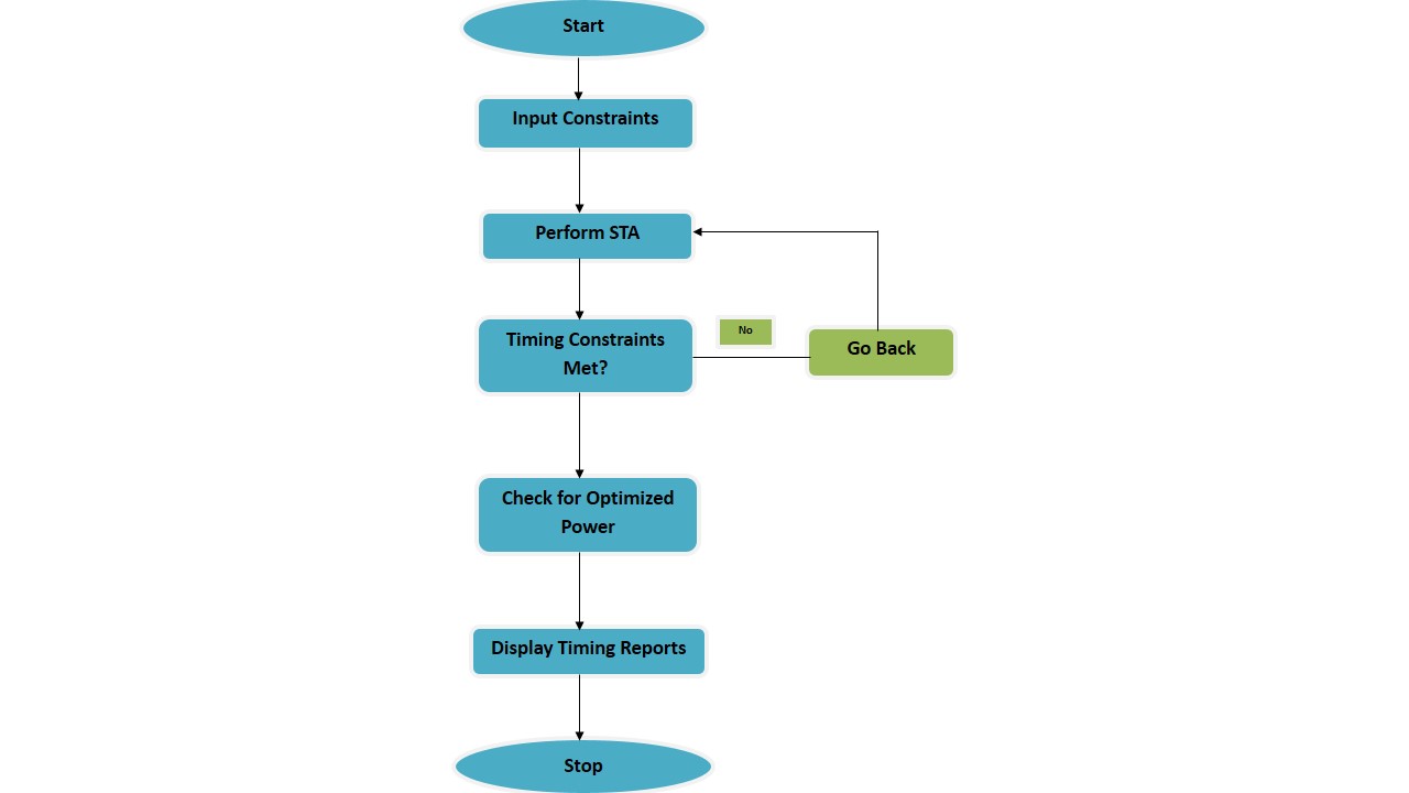
Fig. 4: Stages of STA
Stages at which STA is Performed
STA is implemented after every stage in the complete backend flow of a design. After every stage in backend Design Flow, the Design must be checked for any violations and should be corrected if violations are present. It is important to perform STA after every stage because if we proceed to the next stages without clearing the timing violations of the previous stage then, at the last stage i.e. Routing stage we will end up with a design full of timing violations which will be more complex to correct and will consume a good amount of time to clear those violations after the routing stage.
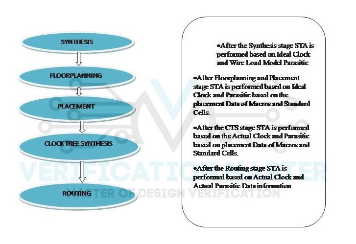 Fig. 5: ASIC development Flow
Ideal Clock
In case of Ideal Clock there is no clock distribution tree all over the design. The clock signal is assumed to be present on time at all the clock pins. Actual clock comes into play only after CTS stage. So, before the Clock Tree Synthesis (CTS) stage, the Ideal Clock is considered.
Wire Load Models
It estimates the effect of interconnect length and the fanout on the Resistance Value, Capacitance Value ,and Area of Interconnect. WLM is used at the Synthesis stage to perform Timing Analysis and Optimization because at the Synthesis stage no physical implementation of chip is done thus, no parasitic information is present at the synthesis stage.
So, from this Blog you can answer the below questions:-
- Q1) What are the Inputs and Output files required for performing STA?
- Q2) Give brief information of files used for performing STA.
- Q3) What are the EDA tools to perform STA and DTA ?
- Q4) Define STA Flow.
- Q5) What are the various stages at which STA is performed?
- Q6) What is an Ideal Clock? What is WLM? Explain in brief