Mainly the delay of a circuit can be put into two types of Delay i.e. Net Delay and Cell Delay.
Net is defined as the wire connecting the Output Port of one Standard Cell or Block to the Input Port of another Standard Cell or Block. Note that a Net has only one Driver Cell/Block, several fanout Cells, and can pass through multiple Metal Layers.
The time taken in charging and discharging the parasitic elements of a Net i.e. Resistive, Capacitive, and inductive Load is referred to as Net Delay. So, Net Delay has three Components i.e. Net Resistance, Net Capacitance, and the Net Topology used.
For calculating the Net Delay we can Model the Wires in many ways. But, remember that when you apply a specific Delay Model in a Design then you must apply that Delay Model for all the Standard Cells in the Library. No two Delay Models be mixed in one Library.
The selection of Delay Models depends on the Technology of the Design, the Stage at which the Delay model is applied, and the accuracy of Delay you want.
Before the Physical Implementation of Actual Routing Wires, we don’t have actual interconnect delay information. So, we use Delay Models for approximate calculations of Delay. Delay Models can be classified in the below categories:
- Lumped Capacitor Model
- Lumped RC Model
- Distributed RC Model
- Pi RC Network
- T RC Network
- RLC Model
- Wire Load Model
- Elmore Delay Model
Lumped Capacitor Model
In Higher Technologies (above 350 nm) Metal Wires were wide and have more cross-sectional area. So, the Resistance factor in higher technologies was considered negligible. Only Capacitance was considered because it was dominating factor in Higher Technologies. In Lumped Capacitor Model, Source Driver considers a single Loading Capacitance that is the submission Interconnect Capacitance and Load Capacitance at Sink Point. Refer Fig.1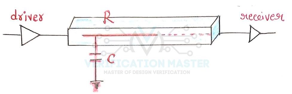
Fig. 1: Lumped Capcitor Model
Lumped RC Model
The decrease in nm Technology which leads to reducing the width of Metal Wires Resistance no longer can be neglected. So, Resistance also needs to be modeled. So, in this case, Lumped RC Model comes into play. In Lumped RC Model total Resistance is Lumped into a single Resistor for each segment of wire along with the total Capacitance lumped into a single Capacitor. Refer Fig.2
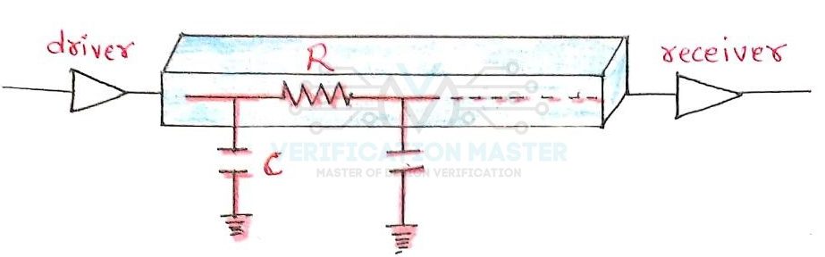
Fig. 2: Lumped RC Model
Distributed RC Model
When the Resistance and Capacitance are taken separately for each Length of Wire then it is referred to as Distributed RC Model. Let’s consider Cp and Rp as Capacitance per unit length and Resistance per unit length respectively and L be the length of wire. Then C total and R total is given by:
C total = Cp*L
R total = Rp*L
-
Pi Model
Total Resistance is present in between the Capacitance and total Capacitance is divided into two parts and connected on either side of Resistance. Refer Fig.3a
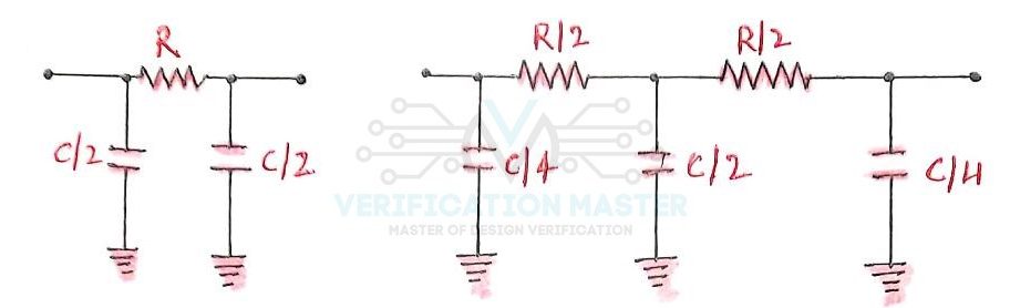
Fig. 3a: Pi Model
-
T Model
Total Resistance is divided into two parts and total Capacitance is considered at the mid-point of the two Resistances. Refer Fig.3b
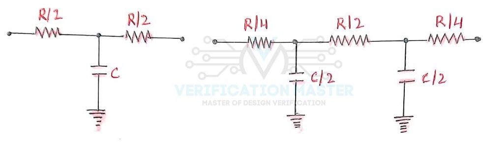
Fig. 3b: T Model
RLC Model
When Design was operating at a lower frequency then impedance was not considered because Resistance dominated Impedance. But, when using a higher frequency of operation and wider Metal Wires in that case Inductance comes into consideration and requires modeling. So, RLC Model is used to model Resistance, Capacitance, and Inductance all three. Refer Fig.4
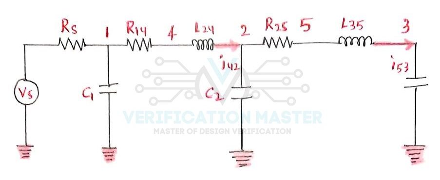
Fig. 4: RLC Model
Wire Load Models
WLM is used to estimate delay in the pre-layout phase of the design cycle and it is different for different technologies. WLM specifies the effect of Length of Wire and Fan-out on the Resistance, Capacitance, and Area of Nets. Resistance, Capacitance, and Area are taken per unit length of Wire. A set of tables is obtained between Net Fan-out vs Load, Net Fan-out vs Resistance, and Net Fan-out vs Area.
For Example, consider the below table
| Number of Fan-out | Resistance (Kohm) | Capacitance (pF) |
| 1 | 0.00498 | 0.00312 |
| 2 | 0.01295 | 0.00812 |
| 3 | 0.02092 | 0.01312 |
| 4 | 0.02888 | 0.01811 |
Types of WLM:
There are three types of WLM when we are performing timing-based optimization before the placement stage, these are:
- Standard WLM:
Based on average of different similar designs.
- Structural WLM
In this rather than just using fan-out and module size information, information about neighboring nets is also used.
- Custom WLM
Based on current design after placement and routing, but before the current iteration of pre-placement synthesis.
Wire Load Model for Synthesis
- Top
Apply the same WLM for all the Nets of the Design. Consider the Design has no hierarchy.
- Enclosed
The WLM of the smallest design that fully encloses a net is applied. More accurate than Top mode.
Segmented
WLM for each segment of the Net is determined by design encompassing each segment. There are different segments for Nets crossing hierarchical boundaries.

Fig. 5: WLM for Synthesis
Elmore Delay Models
Elmore Delays are applicable for RC trees. Rc tree satisfy the below three conditions:
- It has only one input node
- No resistive loops are present
- All Capacitance is between node and ground
In Elmore Delay Model, delay through each segment is calculated as R times the downstream capacitance and then submission of all delays from root to sink.
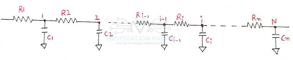
Fig. 6: Elmore Delay Model
In the above Fig.6 the delays will be given as:
Td1 = C1*R1
Td2 = C2*R1 + C2*(R1+R2)
Tdn = ∑ (i=1,N) C1 (∑ (j=1,i) Rj) **Elmore Delay Equation
Pre-layout Timing
During the pre-layout timing verification, interconnect parasitic are estimated using WLM. In many cases, resistance is considered negligible i.e. 0. So, the delay calculation is completely based on capacitive load.
When the resistance of interconnect is considered, in such cases NLDM (Non-linear delay model) is used with total net capacitance for the delay through the cell. When resistance is considered, there is an additional delay from the output pin of the driving cell to the input pin of the fanout cell.
Post-layout Timing
During Post-layout timing verification actual delay of the interconnect parasitics is present. So, the parasitics of the metal trace map into the RC network between the driver and the destination cell.
So from this blog, you can answer the below set of questions:
- Q1) What are interconnect delay models and why are they used?
- Q2) What are the categories of Interconnect Delay Models?
- Q3) What are Wire Load Models and their types?
- Q4) What are the different modes of Wire Load Models?
- Q5) What is the Elmore Delay Model?
- Q6) Discuss pre-layout timing verification and post-layout timing verification.