In Static Timing Analysis, every Timing Path is checked for Setup and Hold Analysis to get an Optimized Design in terms of Timing and meeting the Timing Constraints. But, some Timing Paths need not be Optimized for Timing and STA does not perform Timing Analysis for those Paths. Such Paths are referred to as False Paths. In short, ” A false path is generated when a transition on start point cannot be propagated to the endpoint. Both clock path and data path logics are considered in the determination of a false path.
Examples of False Paths
Case 1: Architectural
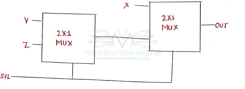
Fig. 1: Example of False Path Architectural
In the above Fig. 1 let us consider the top Select Line as 1 and bottom Select Line as 0. So, when SEL is 0 output of the first Multiplexer is Z, and the output of the second Multiplexer is also Z thus Z is reflected at the output OUT. Now when SEL is 1 output of the first Multiplexer is Y and the output of the second Multiplexer is X thus X is reflected at output OUT. So, in both the cases i.e. when SEL is 0 and 1 Y is not reflected at output OUT. There will never be a valid path between Y and OUT. This will be considered as a False Path.
Case 2: Synchronizers
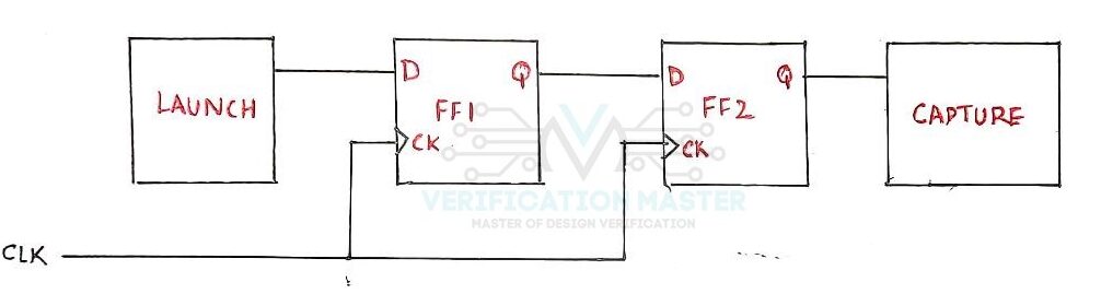
Fig. 2: Example of False Path Synchronizers
Let us consider a case of a two Flip-Flop-based Synchronizer. This synchronizer circuit is placed between Launch Flop and Capture Flop. In this case, it is not important to meet the Timing of Signal coming at FF1 as even if the Signal coming to FF1 is in Metastable State, it will get resolved before the next Active Clock Edge. So, the path traversed by the signal coming from Launch flop to FF1 is considered as a case of False Path.
Synchronizer is a digital circuit that is used to covert an asynchronous signal coming from another clock domain into the recipient clock domain so that it can be captured without metastability.
Case 3: Static Signals
Refer to Fig.3 Let us consider a Multiplexer. There are two modes i.e. 0 and 1 and the Multiplexer output is different for the two modes, thus output path is also different for the two modes. We have to keep mode select bit unconstrained, so that timing for both the modes can be covered. This results in path being formed through multiplexer select also. Since, select is constant for both the modes so path traced through select bit of multiplexer is referred to as False Path, if there are no specific timing requirements associated to mode transition on this signal. Specifically, for the scenario shown in Fig.2
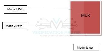
Fig. 3: Example of Static Signals
Case 4: Asynchronous False Path
When the clock domains of the launch register and the capture register are different, then it is considered as an asynchronous circuit. And the path between these two clock domains is considered as the Clock Domain Crossing path. So, in a CDC (Clock Domain Crossing) path, there is no defined relationship between the clock edges of launch and the capture clock domains, so having a timing path is not possible in this case. So, this path can be considered a false path. In this case, setup/hold violations should be taken special care of and avoided.
Commands to define False Path
- SDC command to specify False Path
set_false_path
- From Register to Register
set_false_path -from regA -to regB
- Path being launched from one clock and being captured at another
set_false_path -from [get_clocks clk1] -to [get_clocks clk2]
- Through a signal
set_false_path -through [get_pins AND1/B]
So from this Blog, you can answer the below set of questions:
- Q1) What do you mean by False Paths?
- Q2) Give examples of False Paths.
- Q4) What is an Asynchronous False Path?
- Q5) Commands to define False path.