This blog will start this new topic with a user-defined primitive, also known as UDP.
As part of the language, Verilog includes a standard set of primitives such as and, nand, or, nor, and not. These are also referred to as built-in primitives.
Designers, on the other hand, like to employ their custom-built primitives when constructing a design. User-Defined Primitives (UDP) allow you to define them.
These primitives are self-contained and do not require the instantiation of any other modules or primitives. UDPs are created in the same way that gate-level primitives are.
UDPs are classified into two types: combinational and sequential.
- Combinational UDPs have outputs that are determined solely by a logical combination of the inputs.
- Sequential UDPs use the current input and output values to calculate the value of the next output. The output value is also the UDP’s internal state.
UDP Basics
Let’s look at the various components of the UDP definition.
// UDP name and terminal list
primitive <udp_names> (
<output_terminal_name>(only one allowed)
<input_terminal_names>);


// terminal declarations
output<output_terminal_names>;
input<input_terminal_names>;
reg <output_terminal_name>;(optional; only for sequential UDP)


//UDP initialization
initial<output_terminal_name>=<value>;
//UDP state table
table
    < table entries>
endtable


// End of UDP definition
endprimitive
The term “primitive” is used to begin a UDP definition. The name of the primitive, as well as the output and input terminals, are supplied. In the terminal declarations section, terminals are designated as output or input.
The output terminal of a sequential UDP is stated as a reg. There is an optional start statement for successive UDPs that initialises the UDP’s output terminal.
The most significant aspect of the UDP is the state table. It starts with the keyword table and finishes with the keyword and table.
The table specifies how the output will be calculated based on the inputs and current state. The table is designed to be a lookup table. and the table entries are similar to logic truth table entries The keyword and finishing the primitive definition.
UDP rules
Certain rules govern UDP definitions.
- Only scalar input terminals can be used by UDPs (1 bit). Multiple input terminals are permitted.
- UDPs are limited to a single scalar output terminal (1 bit). The output terminal must always be listed first in the terminal list. Multiple output terminals are not permitted.
- The output terminal is specified in the declarations section using the keyword output. Because sequential UDPs preserve state, the output terminal must also be specified as a reg.
- The inputs are defined using the keyword input.
- An initial statement may be used to initialise the state in a sequential UDP. This statement is optional. The output is allocated a 1-bit value, which is designated as reg.
- The entries in the state table can have the values 0, 1, or UDPs do not handle values. I values sent to a UDP are interpreted as x values.
- UDPs are specified at the module level. UDPs cannot be specified within modules. They can only be created within modules. UDPs are created in the same way as gate primitives are.
- Input ports are not supported by UDP.
The following principles apply to both combinational and sequential UDPs.
The next sections will go into the specifics of combinational and sequential UDPs.
Combinational UDP
Combinational UDPs receive inputs and generate output values by searching the state table for the relevant item.
The most significant aspect of the UDP specification is the state table. A state table is best explained with the example of and and the gate portrayed as a UDP.
Instead of utilising Verilog’s and gate primitives, let us define our own and gate primitives and call them udp_and.
primitive udp_and(out, a, b); 	//primitive terminal
output out; 			// not declared as reg in combinational UDP
input a, b; 			//input
//a	b	:	out;	//state table definition
0	0	:	0;
0	1	:	0;
1	0	:	0;
1	1	:	1;
endtable			// end state table
endprimitve			//end udp_and
Each item in a combinational UDP’s state table contains the following pseudosyntax.
<in1> <in2> ……… <inN> : <out>;
Sequential UDP
In both definition and behaviour, sequential UDPs differ from combinational UDPs. Sequential UDPs differ in the following ways:
- A sequential UDP’s output is always stated as a reg.
- To initiate the output of successive UDPs, use an initial statement.
- A state table entry has a somewhat different format.
<in1> <in2> …… <inN> : <current_state> : <next_state>;
- A state table item is divided into three sections: inputs, current state, and next state. A colon (:) sign separates the three components.
- State table entries can be specified in terms of input levels or edge transitions.
- The current state is the output register’s current value.
- Based on the inputs and the current state, the future state is calculated. The next state becomes the output register’s new value.
- To avoid unexpected output values, all potential input combinations must be described.
Level-Sensitive Sequential UDPs
Level-sensitive UDPs modify their status in response to input levels. The most common type of level-sensitive UDP is a latch. Figure 1 depicts a basic latch.
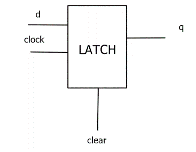
Fig 1: D Latch
If the clear input is 1, the output q of the level-sensitive latch is always o.
When clock=1, q=d if clear is 0. If clock equals zero, q keeps its value. As demonstrated in, the latch may be defined as a UDP.
Let’s see the Verilog of the above D latch along with the stimulus
primitive d_latch (q, clk, d);
    output  q;
    input   clk, d;
    reg     q;

    table
                 // clk     d       q   q+
            1   1   :   ? : 1;
            1   0   :   ? : 0;
            0   ?   :   ? : -;
    endtable

endprimitive
module tb;
  reg clk, d;
  reg [1:0] dly;
  wire q;
  integer i;

  d_latch u_latch (q, clk, d);

  always #10 clk = ~clk;

  initial begin
    clk = 0;

    $monitor ("[T=%0t] clk=%0b d=%0b q=%0b", $time, clk, d, q);

    #10;                               // monitoring

    for (i = 0; i < 50; i = i+1) begin
      dly = $random;
      #(dly) d <= $random;
    end

    #20 $finish;
  end
endmodule
In figure 2 respective output is shown:
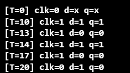
Fig 2: Output of D Latch
Edge-Sensitive Sequential UDPs
Edge-sensitive sequential UDPs alter their state in response to edge transitions and/or input levels. The most frequent example of edge sensitive sequential UDPs is edge-triggered flip-flops. Figure 2 depicts a negative edge-triggered D-flipflop with clear.
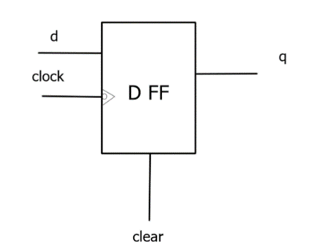
Fig 3: D flipflop
If clear = 1, the output q of the edge-sensitive flip-flop illustrated above is always 0.
If clear=0, the D-flipflop operates properly. On the negative edge of the clock, i.e., the transition from 1 to 0, q receives the value of d.
If the clock switches to an unknown state or on the positive edge of the clock, do not modify the value of q. Also, if d changes, hold the value of q when the clock is steady.
The description for the D-flipflop is shown below:
primitive d_flop (q, clk, d);
    output  q;
    input   clk, d;
    reg     q;

    table
                               // clk         d         q       q+
            // rising edge of clk
            (01)    0   :   ?   :   0;
            (01)    1   :   ?   :   1;
            (0?)    1   :   1   :   1;
            (0?)    0   :   0   :   0;

            // ignore negative edge of clk
            (?0)    ?   :   ?   :   -;

            // ignore data changes on steady clk
            ?       (??):   ?   :   -;
    endtable

endprimitive

D- flipflop stimulus is shown below:
module tb;
  reg clk, d;
  reg [1:0] dly;
  wire q;
  integer i;

  d_flop u_flop (q, clk, d);

  always #10 clk = ~clk;

  initial begin
    clk = 0;

    $monitor ("[T=%0t] clk=%0b d=%0b q=%0b", $time, clk, d, q);

    #10;  // monitoring

    for (i = 0; i < 20; i = i+1) begin
      dly = $random;
      repeat(dly) @(posedge clk);
      d <= $random;
    end

    #20 $finish;
  end
endmodule
The output of the following verilog of D-flipflop is shown in figure 4.
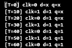
Fig 4: Output of D- flipflop
So, after reading this blog, we clearly understand all the basics of UDPs.
So let’s summarise the whole blog in a few questions:
- What exactly are user-defined primitives?
- What are the parts of UDPs?
- What are the UDP rules?
- How many different kinds of UDPs are there?
- What exactly is combinational UDP?
- What exactly is sequential UDP, and what are the different types?