In today’s blog, we will learn to design a shift unit. But, because jumping right into the design process will not be interesting, let’s start with some shift unit basic knowledge.
Arithmetic Logic Shift Unit
The Arithmetic Logic Shift Unit (ALSU) is a component of a computer system’s Arithmetic Logic Unit (ALU). It is a digital circuit that can execute arithmetic, logical, and shift operations.
Instead of using individual registers to conduct microoperations, computer systems use a group of storage registers linked to a common operational unit known as an arithmetic logic unit, abbreviated ALU.
The ALSU is made up of arithmetic, logic, and shift circuits. The circuit can do 8 arithmetic operations, 16 logical operations, and 2 shift operations at each stage.
The ALSU is responsible for the following conditions: equal to, less than, and greater than.
Shift Operators
Right shift (>>) and left shift () are shift operators. These operations shift a vector operand by a defined number of bits to the right or left. The vector and the number of bits to shift are the operands. The unoccupied bit locations are filled with zeros when the bits are changed. Shift activities are not circular.
// X = 4’b1100
Y= X >> 1 ;		// Y is 4’b0110 right shift 1 bit and 0 is filled in MSB position.
Y = X << 1;		// Y is 4’b1000 left shift 1 bit and 0 is filled in LSB position.
Shift operators are useful because they enable designers to model shift operations, shift-and-add multiplication algorithms, and other relevant operations.
Now we will see some facts about shift operators in Verilog.
Left Shift
To shift the bits to the left, Verilog includes a left shift operator, i.e., “<<“. You can specify how many bits must be shifted.
Let’s have an example to clear more facts about left shift.
module test;

  reg[3:0] x;

  initial
    begin
    	x =4'b1100;
    $display("x before shift = %4b",x);
     x = x<<2;
    $display("x after shift = %4b",x);
    end

endmodule
The output of the following code is shown below in figure 1.
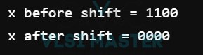
Fig 1: Left Shift Output
The statement
x = x<<2;
x shift two spaces to the left. This example yields the results x before shift = 1100 and x after shift = 0000.
Following the shift, the LSB bits are padded with 0s.
The value may be kept if the variable on the left side of the assignment statement is larger than the variable on the right side of the assignment.
Right Shift
The >> character is used to move the bits to the right. Following the shift, the MSB bits are padded with 0s.
As an illustration, in
x = 4'b1100;
x = x>>1;
After the two statements, the value of x is 0’b0110.
When using the right shift operator, the bits moved out of the right side do not need to be saved.
Let me illustrate this with an appropriate example.
module test;

  reg[3:0] x;
  reg[5:0] y;

  initial
    begin
    	x =4'b1100;
    $display("x before shift = %4b",x);
     y = x>>3;
      $display("y after shift = %6b",y);
    end

endmodule
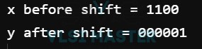
Fig 2: Right Shift output
There is no surprise, and the outcome is
x before shifting = 1100
y shift post = 000001
The least significant bits are always lost when using the right shift operator.
We will see the 8 bit barrel shifter verilog code and we will know interesting facts related to it.
8 bit Barrel Shifter Verilog Code
In this section, we will share the Verilog code for a barrel shifter with you. In contrast to normal shifters, which are sequential circuits, a barrel shifter is a combinational circuit.
A register-based shifter requires eight clock cycles to shift an 8-bit value, but a barrel shifter requires only one clock cycle. It is used in ALU for shifting operations.
The following is a generic block diagram of a mux-based barrel shifter.
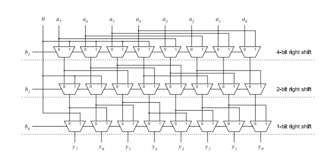
The above barrel shifter has been implemented in Verilog. The Barrel Shifter’s verilog code is shown below.
module barrel_shifter_8bit (in, ctrl, out); 			//8 bit Barrel Shifter Verilog Code
  input  [7:0] in;
  input [2:0] ctrl;
  output [7:0] out;
  wire [7:0] x,y;


//4bit shift right
mux2X1  ins_17 (.in0(in[7]),.in1(1'b0),.sel(ctrl[2]),.out(x[7]));
mux2X1  ins_16 (.in0(in[6]),.in1(1'b0),.sel(ctrl[2]),.out(x[6]));
mux2X1  ins_15 (.in0(in[5]),.in1(1'b0),.sel(ctrl[2]),.out(x[5]));
mux2X1  ins_14 (.in0(in[4]),.in1(1'b0),.sel(ctrl[2]),.out(x[4]));
mux2X1  ins_13 (.in0(in[3]),.in1(in[7]),.sel(ctrl[2]),.out(x[3]));
mux2X1  ins_12 (.in0(in[2]),.in1(in[6]),.sel(ctrl[2]),.out(x[2]));
mux2X1  ins_11 (.in0(in[1]),.in1(in[5]),.sel(ctrl[2]),.out(x[1]));
mux2X1  ins_10 (.in0(in[0]),.in1(in[4]),.sel(ctrl[2]),.out(x[0]));

//2 bit shift right

mux2X1  ins_27 (.in0(x[7]),.in1(1'b0),.sel(ctrl[1]),.out(y[7]));
mux2X1  ins_26 (.in0(x[6]),.in1(1'b0),.sel(ctrl[1]),.out(y[6]));
mux2X1  ins_25 (.in0(x[5]),.in1(x[7]),.sel(ctrl[1]),.out(y[5]));
mux2X1  ins_24 (.in0(x[4]),.in1(x[6]),.sel(ctrl[1]),.out(y[4]));
mux2X1  ins_23 (.in0(x[3]),.in1(x[5]),.sel(ctrl[1]),.out(y[3]));
mux2X1  ins_22 (.in0(x[2]),.in1(x[4]),.sel(ctrl[1]),.out(y[2]));
mux2X1  ins_21 (.in0(x[1]),.in1(x[3]),.sel(ctrl[1]),.out(y[1]));
mux2X1  ins_20 (.in0(x[0]),.in1(x[2]),.sel(ctrl[1]),.out(y[0]));

//1 bit shift right
mux2X1  ins_07 (.in0(y[7]),.in1(1'b0),.sel(ctrl[0]),.out(out[7]));
mux2X1  ins_06 (.in0(y[6]),.in1(y[7]),.sel(ctrl[0]),.out(out[6]));
mux2X1  ins_05 (.in0(y[5]),.in1(y[6]),.sel(ctrl[0]),.out(out[5]));
mux2X1  ins_04 (.in0(y[4]),.in1(y[5]),.sel(ctrl[0]),.out(out[4]));
mux2X1  ins_03 (.in0(y[3]),.in1(y[4]),.sel(ctrl[0]),.out(out[3]));
mux2X1  ins_02 (.in0(y[2]),.in1(y[3]),.sel(ctrl[0]),.out(out[2]));
mux2X1  ins_01 (.in0(y[1]),.in1(y[2]),.sel(ctrl[0]),.out(out[1]));
mux2X1  ins_00 (.in0(y[0]),.in1(y[1]),.sel(ctrl[0]),.out(out[0]));

endmodule

//2X1 Mux
module mux2X1( in0,in1,sel,out);
input in0,in1;
input sel;
output out;
assign out=(sel)?in1:in0;
endmodule


The 8-bit Barrel Shifter test bench is shown below.


module barrel_shifter_8bit_tb;
  reg [7:0] in;
  reg [2:0] ctrl;
  wire [7:0] out;

barrel_shifter_8bit uut(.in(in), .ctrl(ctrl), .out(out));

initial
 begin
    $display($time, " << Starting the Simulation >>");
        in= 8'd0;  ctrl=3'd0; //no shift
    #10 in=8'd128; ctrl= 3'd4; //shift 4 bit
    #10 in=8'd128; ctrl= 3'd2; //shift 2 bit
    #10 in=8'd128; ctrl= 3'd1; //shift by 1 bit
    #10 in=8'd255; ctrl= 3'd7; //shift by 7bit
  end
    initial begin
      $monitor("Input=%d, Control=%d, Output=%d",in,ctrl,out);
    end
endmodule
The output of the following 8-bit barrel shifter is shown below in figure 3
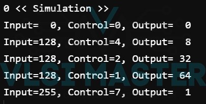
Fig 3 8-bit Barrel Shifter output
This was a very interesting blog based on shift unit design. So, in a few questions, let’s summarise the entire blog.
- How to design a shift unit in Verilog?
- What do you mean by “shift operators”?
- Create and explain the Left and Right Shift.
- What do you mean by 8-bit barrel shifter Verilog code?
- How to design an 8-bit barrel shifter in Verilog code?