This is an interesting blog and somehow unique as well, so we will discuss it now. We know about the traffic light controller,but let’s start with the beginning.
The primary function of traffic control signals is to assign right-of-way at intersections where a continuous flow of cars on one lane would cause significant delay for vehicles and/or pedestrians waiting on the other.
Let us first acknowledge that FSM is critical in the TLC.
Finite State Machine
Finite state machines (FSMs) are important for comprehending decision making logic and controlling digital devices.
In the FSM, it contains the outputs that, along with the next state, are a present state and an input function. This means that the following state is mostly governed by the input value and strength, resulting in better compound system performance.
As in sequential logic, we need the history of previous inputs to determine the result. As a result, FSM is quite helpful in comprehending sequential logic jobs.
Types of FSM
There are two types of finite state machines: Mealy state machines and Moore state machines.
Moore state machines
When the outputs are determined by current states, the FSM is referred to as a Moore state machine.
In this situation, the current inputs and states will determine the following states: As a result, depending on the subsequent states, this machine will create the outputs.
As a result, the outputs of this will be applicable only once the state has been converted.
Mealy state machines
When the outputs are dependent on the current inputs as well as the states, the FSM is referred to as a mealy state machine.
This machine can generate outputs based on the current inputs and states. As a result, the outputs can only be suitable when the CLK signal is positive, otherwise it is negative.
Let’s discuss the FSM with the specification of TLC.
Specification of TLC
Consider a traffic controller at the junction of a major highway and a rural road. Some of the following considerations must be made:
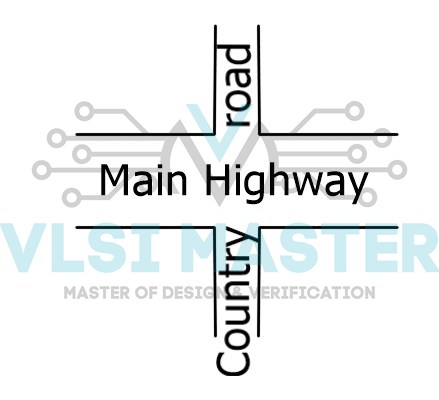
Fig 1: Specification of TLC
Because automobiles are always present on major roadways, the traffic light for the main highway receives the most attention. As a result, the primary roadway signal remains green by default.
Occasionally, cars from the rural road stop at the traffic light.The country road traffic light must turn green only long enough to allow the automobiles on the country road to proceed.
When there are no automobiles on the country roads, there is no country road traffic.The traffic signal on the main highway turns yellow, then red, and finally back to green.
A sensor detects automobiles waiting on the rural road. The sensor delivers a signal X to the controller as input.
If there are automobiles on the rural road, X equals one; otherwise, X equals zero.
Transitions from S1 to S2, S2 to S3, and S4 to S0 are all delayed. Delays must be manageable.
Figure 2 depicts the traffic signal controller’s state machine diagram and state definitions.
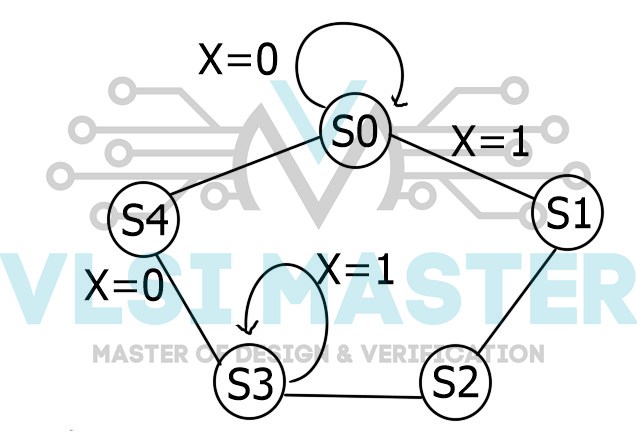
Fig 2: FSM of TLC
| State | Signals |
| S0 | Hwy = G Cntry =R |
| S1 | Hwy = Y Cntry =R |
| S2 | Hwy = R Cntry =R |
| S3 | Hwy = R Cntry =G |
| S4 | Hwy = R Cntry =Y |
Verilog
As demonstrated below, the traffic signal controller module may be constructed using behavioural Verilog components.
`define TRUE 1'b1
`define FALSE 1'b0
`define RED 2'd0
`define YELLOW 2'd1
`define GREEN 2'd2
`define S0 3'd0
`define S1 3'd1
`define S2 3'd2
`define S3 3'd3
`define S4 3'd4
`define Y2RDELAY 3
`define RZGDELAY 2

module sig_control(hwy, cntry, X, clock, clear);
  output [1:0] hwy, cntry;
  reg [1:0] hwy, cntry;
  input X;
  input clock, clear;
  reg [2:0] state;
  reg [2:0] next_state;
  initial  begin
    state = `S0;
    next_state = `S0;
    hwy = `GREEN;
    cntry = `RED;
  end

  always @(posedge clock)
    state = next_state;

  always @(state)  begin
    case (state)
      `S0 : begin
              hwy = `GREEN;
              cntry = `RED;
            end
      `S1 : begin
              hwy = `YELLOW;
              cntry = `RED;
            end
      `S2 : begin
              hwy = `RED;
              cntry = `RED;
            end
      `S3 : begin
              hwy = `RED;
              cntry = `GREEN;
            end
      `S4 : begin
              hwy = `RED;
              cntry = `YELLOW;
            end
    endcase
  end

  always @(state or clear or X)  begin
    if (clear)
      next_state = `S0;
    else
      case (state)
        `S0: if ( X)
               next_state = `Sl;
             else
               next_state = `S0;
        `S1: begin
               repeat(`Y2RDELAY) @(posedge clock) ;
                 next_state = `S2;
             end
        `S2: begin
               repeat ( `R2GDELAY) @ (posedge clock)
                 next_state = `S3;
             end
        `S3: if( X)
               next_state = `S3;
             else
               next_state = `S4;
        `S4: begin
               repeat(`Y2RDELAY) @(posedge clock) ;
                 next_state = `S0;
             end
        default: next_state = `S0;
     endcase
   end
endmodule
When automobiles arrive on a country road, stimuli can be used to verify if the traffic signals transition appropriately. The stimulus below instantiates the traffic signal controller and checks all of its potential states.
module stimulus;
  wire [1:0] MAIN_SIG, CNTRY_SIG;
  reg CAR_ON_CNTRY_RD;
  reg CLOCK, CLEAR;
  sig_control SC(MAIN_SIG, CNTRY_SIG, CAR_ON_CNTRY_RD, CLOCK, CLEAR);
  initial
    $monitor($time, " Main Sig = %b, Country Sig = %b, Car-on-cntry = %b",MAIN_SIG, CNTRY_SIG, CAR_ON_CNTRY_RD) ;
  initial begin
    CLOCK = `FALSE;
    forever #5 CLOCK = -CLOCK;
  end

  initial begin
    CLEAR = `TRUE;
    repeat (5) @(negedge CLOCK)
    CLEAR = `FALSE;
  end
  initial  begin
    CAR_ON_CNTRY_RD = 'FALSE;
   #200 CAR_ON_CNTRY_RD = 'TRUE;
   #100 CAR_ON_CNTRY_RD = 'FALSE;
   #200 CAR_ON_CNTRY_RD = 'TRUE;
   #100 CAR_ON_CNTRY_RD = 'FALSE;
   #200 CAR_ON_CNTRY_RD = 'TRUE;
   #100 CAR_ON_CNTRY_RD = 'FALSE;
   #100 $stop;
  end
endmodule
Hence, we are able to design traffic light control with the help of Verilog, but we have ignored all the other designing processes.
Difference between mealy and moore model
We will solely discuss how the Mealy and Moore models affect TLC programming and design.
As seen above, changes in the information can impact the output of the circuit in the Mealy model, whereas changes in the input have no effect on the output of the circuit in the Moore model.
We are well aware that in the mealy model, it takes fewer states to implement the same function. However, Moore models require a greater number of states to achieve the same function as the same case in TLC also.
The output is a function of both the current state and the current input, and the counter cannot be called a Mealy Machine.
However, under the Moore model, the output is a function of the current state, and the counter is referred to as a Moore Machine. This is the primary distinction between the Mealy and Moore FSM models.
The Mealy model’s architecture is sophisticated when compared to the TLC example or any other, and Mealy machines react to changes faster since they all appear to react in the same way.
Within mealy models If the external inputs change, the output may change between clock edges.
However, this is not the case in The Moore model’s architecture is simple since the output is set on the transition.
In Moore decoding, more logic is required, resulting in greater circuit delays. They typically respond after one clock cycle. The output will change only when the active clock edge changes.
Moore has The output has been set to state, and its hardware is required for design.
So let’s summarise the whole blog with a few questions so that the topic of this blog will be crystal clear.
- What is a traffic light controller?
- What do you mean by FSM?
- How is FSM used in TLC?
- How many types of FSM?
- What changes will occur in TLC if it is based on the Moore model?