In this blog, we will learn how to design MISR, or Multiple Input Signature Register, in Verilog, but first, we should understand what MISR is. So, let’s start a blog in a fresh and exciting way.
In working in individual test (BIST) strategies, putting away all the circuit yields on a chip isn’t feasible, but the circuit yield might be condensed to frame a mark that will later be contrasted with the brilliant mark (of the great circuit) to identify difficulties.
Because this pressure is lossy, there is always the possibility that a faulty yield makes an indistinguishable mark from the dazzling mark, and the faults can’t be addressed.
This is known as error hiding or associating. BIST is knowledgeable about a number of information signature enrolments (MISR or MSR), which is a type of LFSR.
A typical LFSR contains a single XOR or XNOR door, where the contribution of the door is related to a few “taps” and the yield is related to the contribution of the main flip-slump.
As a result, the following MISR condition is based on the previous several states, as opposed to merely the current state. As a result, if the information sequence is consistent, a MISR will consistently create the same bright mark.
Design
Let’s take a look at the Multiple Input Signature Register design in Figure 1 and discuss some facts about it.
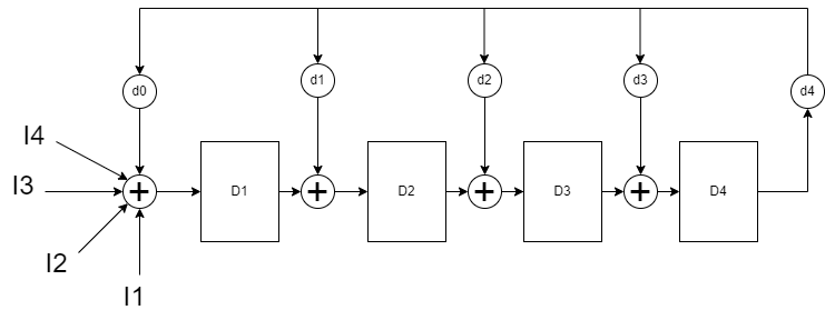
Fig 1: Multiple input signature register
As a result, the following MISR condition is based on the previous several states, as opposed to merely the current state. As a result, if the information sequence is consistent, a MISR will consistently create the same bright mark.
A multiple-input signature register is required for a multiple-output digital system. This register speeds up testing by combining several input data streams into a single signature.
Existing designs rely on passing the input polynomials to the storage elements in parallel. These designs provide good compression but have several downsides. The work given here suggests a novel architecture for a multiple-input signature register.
At a particular point, the suggested device combines all the inputs and passes them to the shift register. We can enhance the functionality of the multiple input signature register in a variety of ways by using this approach.
The advantages of the new structure were validated by complete VHDL modelling and simulation for the existing and proposed designs.
Verilog
Below is the Verilog of the following MISR which we discussed above.
module misr(clk,rst,m);
    input clk;
    input rst;
    input [4:0] m;
    reg q4,q3,q2,q1,q0;
    reg [4:0] count;
    reg [4:0] disp;
        initial begin
            q0 = 1'b0;
            q1 = 1'b0;
            q2 = 1'b0;
            q3 = 1'b0;
            q4 = 1'b0;
            count = 5'b0;
        end
            always @(posedge clk)
            begin
             if(rst==1)
             begin
                 q0=1'b0;
                 q1=1'b0;
                 q2=1'b0;
                 q3=1'b0;
                 q4=1'b0;
                 end
                 end
        always @(posedge clk &&rst == 0)
        begin
            q0<=q4^m[0];
            q1<=q0^q4^m[1];
            q2<=q1^m[2];
            q3<=q2^m[3]^q4;
            q4<=q3^q4^m[4];
        end

        always @(posedge clk)
            begin
             disp = {q0,q1,q2,q3,q4};
             $display("%b",disp);

        end
    endmodule
Testbench
Below is the testbench of the following MISR which we discussed above.
module misr_tb();
     reg clk1,rst;
     reg [4:0]m;
    reg [4:0]count;
    misr dut (clk1,rst,m);
              initial
               begin
                 m = 5'b0;
                 clk1 = 1'b0;
                 count = 5'b0;
                 rst = 1'b0;
                 end

            initial
             begin
               #1
               m[4:0] = 5'b10111;
               clk1 = clk1 +1;
               #1
               clk1 = clk1+1;

               #1
               m[4:0] = 5'b01001;
               clk1 = clk1 +1;
               #1
               clk1 = clk1+1;

               #1
               m[4:0] = 5'b01110;
               clk1 = clk1 +1;
               #1
               clk1 = clk1+1;

               #1
               m[4:0] = 5'b01101;
               clk1 = clk1 +1;
               #1
               clk1 = clk1+1;

               #1
               m[4:0] = 5'b10010;
               clk1 = clk1 +1;
               #1
               clk1 = clk1+1;

               #1
               m[4:0] = 5'b10010;
               clk1 = clk1 +1;
               #1
               clk1 = clk1+1;
               #1

               clk1 = clk1+1;
               #1
               clk1 = clk1+1; //at 0 presently
               #1
               rst = 1'b1;
               m[4:0] = 5'b0;
               #1
               clk1 = clk1+1;
               #1
               clk1 = clk1 +1;
               rst = 1'b0;

               #1
               m[4:0] = 5'b11110;
               clk1 = clk1 +1;
               #1
               clk1 = clk1+1;

               #1
               m[4:0] = 5'b01100;
               clk1 = clk1 +1;
               #1
               clk1 = clk1+1;

               #1
               m[4:0] = 5'b01111;
               clk1 = clk1 +1;
               #1
               clk1 = clk1+1;

               #1
               m[4:0] = 5'b01011;
               clk1 = clk1 +1;
               #1
               clk1 = clk1+1;

               #1
               m[4:0] = 5'b01111;
               clk1 = clk1 +1;
               #1
               clk1 = clk1+1;

               #1
               m[4:0] = 5'b10010;
               clk1 = clk1 +1;
               #1
               clk1 = clk1+1;
               #1
                 clk1 = clk1 +1;
               #1
               clk1 = clk1+1;
             end


    endmodule
Output
Figure 2 shows the output of the above-discussed topic, i.e., MISR.
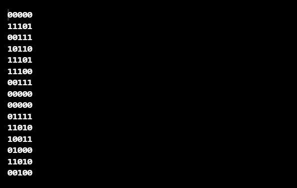
Fig 2: Output of MISR
We learned from today’s blog about the multiple input signature input register, so let’s summarise the whole blog with a few questions that will make all the facts more clear.
- What exactly does MISR do?
- What is the MISR structure?
- How should MISR be designed in Verilog?