Hierarchical Modeling Concept
With the help of our previous blog, we have learned some interesting new facts about Verilog. As a result, let’s talk about one of the first concepts to grasp, namely the hierarchical modelling concept.
To conduct efficient Verilog HDL-based design, the designer must adopt a “good” design process. In this blog, we’ll go through common design techniques and show how they transfer to Verilog. A digital simulation is composed of several components. We will discuss the components and their relationships.
Design methodology
Digital design techniques are classified into two types: top-down design methodologies and bottom-up design methodologies.
Top-Down Methodology
In a top-down design technique, we simply define the top-level block and identify the sub-blocks required to create the top-level block. We further split the sub-blocks until we reach leaf cells, which cannot be divided anymore. The top-down design approach is depicted in Figure 1.
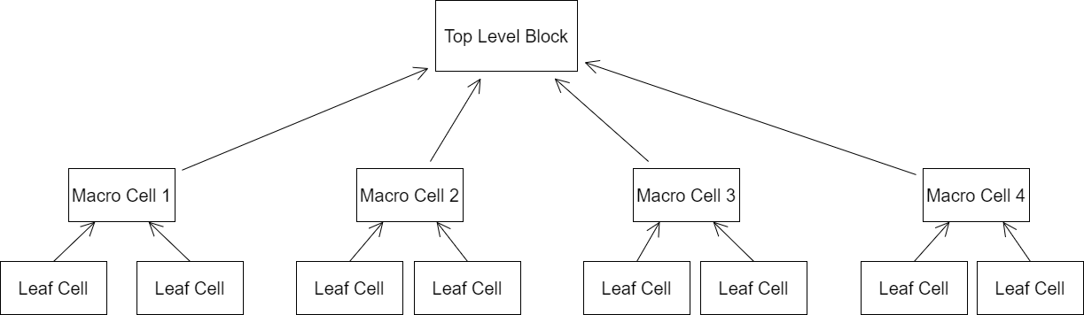
Fig 1: Top-down Design Technique
Bottom-up Methodology
In a bottom-up design technique, we first identify the accessible building pieces. Using these building components, we construct larger cells. These cells are then utilised for higher-level blocks until the design’s top-level block is built. The bottom-up design approach is depicted in Figure 2.
Fig 2: Bottom-up Design Technique
A mix of top-down and bottom-up flows is generally utilized. The requirements of the top-level block are defined by the design architects. Logic designers select how to arrange the design by dividing functionality into blocks and sub-blocks. Simultaneously, circuit designers are developing efficient circuits for leaf-level cells. They use these leaf cells to create higher-level cells.
The flow intersects at an intermediate stage when switch-level circuit designers have used switches to generate a library of leaf cells and logic-level designers have planned from the top down until all modules are specified in terms of leaf cells.
Let us discuss the design of a negative edge-triggered 4-bit ripple carry counter, which will demonstrate these hierarchical modelling approaches in a clear way.
4-bit ripple carry counter
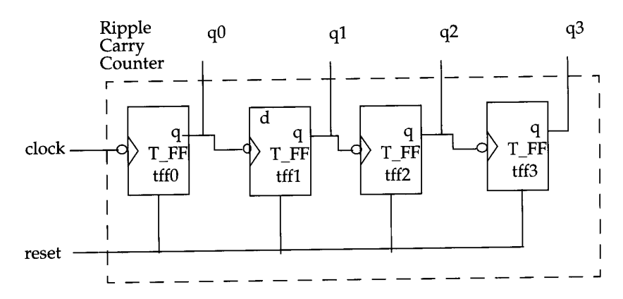 Fig 3: 4-bit ripple carry counter
Figure 3 shows a ripple carry counter consisting of negative edge-triggered toggle flip-flops or T-flipflops. As illustrated in Figure 4, each of the T-flipflops may be built using negative edge-triggered D-flipflops and inverters (assuming the D-flipflops do not have q-bar output).
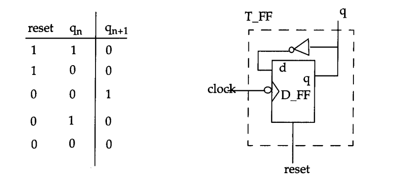
Fig 4: T-flipflops
As a result, the ripple carries counter is constructed in a hierarchical manner using building blocks. Figure 5 depicts the design hierarchy diagram of the ripple counter.
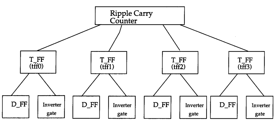
Fig 5: Design Hierarchy Diagram of Ripple Counter
In a top-down design process, we must first identify the functionality of the top-level block, the ripple carries counter. The counter is then implemented using T-flipflops. We construct the T-flipflops using the D-flipflops and an extra inverter gate. After that, we split larger blocks into smaller building sub-blocks until we reach the point where we can no longer break up the Mocks any further.
A bottom-up approach works in the opposite direction. We construct by combining large building components,t,s for example, we might construct D-flipflops out of AND and OR, or we could construct customised D-flipflops form of transistors. Thus, at the level of the D -flipflops, the bottom-up flow meets the top-down flow.
Some aspects of programming that are very important to know first are discussed. Now let’s see what we learned in a while.
- What do you mean by the hierarchical modelling concept?
- How many types of design methodology exist?
- Explain briefly the top-down design technique.
- Describe briefly the bottom-up design technique.
- Explain how both types of design methodologies are used with an example of a 4-bit ripple carry counter.