In physical design, mainly six input present
| Name of input | File Format | Given by |
| Netlist | Verilog(.v) | Synthesis Team |
| Synopsys Design constraints (SDC) | .sdc (written in TCL) | Synthesis Team |
| Logical library/Timing library | .lib | vendors
|
| Physical Library | .lef(library exchange format) | vendors |
| Technology file
|
.techlef/.tf
|
foundry
|
Gate level Netlist :
- This is the synthesized netlist. The synthesis team converts RTL(register transfer level) to gate-level netlist(includes combinational cells, sequential cells, nets, and their connectivity).
- Netlist contains logical connectivity of the standard cells and macros and also provides the details of the nets and their connectivity.
- The common netlist file formats are.v or .vg and .ddc files.
- .v: It contains the net connectivity information between cells and macros, gate-level descriptions of the cells
- .DDC: It contains both the net connectivity information and the scan chain information and gate-level description of the cells.
Example of netlist:
module carry (input a, b, c, output cout)
 wire x, y, z;
 and g1(x, a, b);
 and g2(y, a, c);
 and g3(z, b, c);
 or g4(count x, y, z);
endmodule
Timing library/logical library(.lib)
- It contains the timing information of a standard cell(And gate, or gate, flip-flops, etc.), hard macros(like IP, ROM, RAM, etc.), and soft macros.
- It contains the functionality information of a standard cell and soft macros.
- Timing information like cell delay setup, hold, recovery, removal is present
- Design rules like max tran, max cap, max fan out, min cap are present.
- It also contains power information.
- PVT(Process Voltage and Temperature) corner is also present. The design needs to be tested for certain PVT. But for every PVT corner, the timing of the cells are different. Hence, for every PVT corner, there is a .lib file.
- The information inside the .lib file is divided into two parts:
In the First part, it contains information that is common for all the standard cells
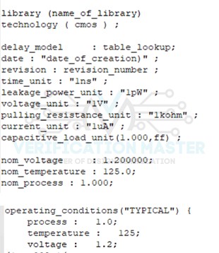
Fig. LIB common part
The common part of the LIB file contains
- Library name and technology name
- Unit (of time, power, resistance, capacitance)
- value of operating condition (Process, voltage, temperature)-Max, Min, Typical
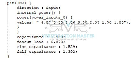
The second part contains cell-specific information for each cell.
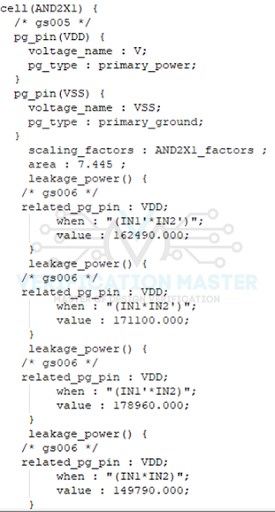
Cell-specific information in the .lib file is mainly
- Cell name
- Area of cell
- Pin name
- Leakage power in respect of input pins
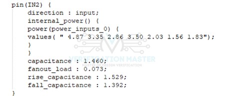
- Pin details
- Pin name
- Pin direction
- Internal Power
- Capacitance
- Raise capacitance
- Fall capacitance
- Fan out load
Library Exchange Format(LEF)
- Lef files are the abstract view of cells. It only gives an idea about, place and route boundary, pin position, metal layer information of the cell.
- Lef file can be categorized into two-part
- Technology LEF
- Cell LEF
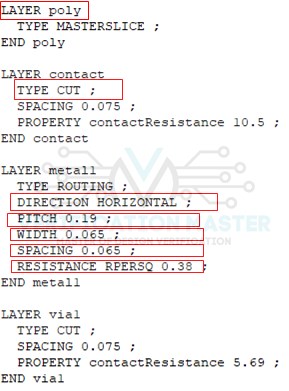
Technology LEF
- Technology LEF files contain information regarding all the metal interconnects, layers of physical information (pitch, width, spacing, direction, etc.), via information and related design rules, Non-Default Rule(NDR).
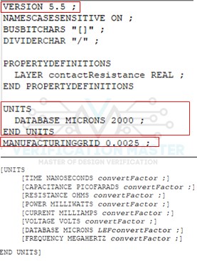
- Techlef file contains below section
- Lef Version(like 5.7 or %.8)
- Units
- Manufacturing Grids
- Design rules and other details of the Back End of the layer
- Layer name (like metal, contact, poly, etc.)
- Layer type (like cut, masterslice, cut, etc.)
- Pitch
- Minimum width
- Spacing
- Sheet resistance
- Direction(like Horizontal or vertical)
Below shows the LEF file for the layer section and different dimension of metal interconnection
Cell Lef
Cell LEF contains the information related to macros and standard cells. Standard cell Lef file is given by foundry, macros LEF file will be given by foundry or third party vendor in case macros/IP are obtained from them.
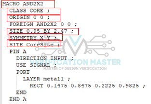
- Cell Lef contain below section
- Cell Name (like NAND2X2 CLKBUF2 etc.)
- Class (like core or pad)
- Origin 0 0
- Size (Width * Height)
- Symmetry (like XY, X, Y etc.)
- Pin information
DEF file
- DEF stands for “Design Exchange Format” file
- DEF was developed by Cadence Design System
- It is used to represent the physical layout of an IC in ASCII format.
- We use Def file along with LEF(Library Exchange Format) to represent the complete physical layout of an integrated while it been design
- The advantage of the DEF file is that we can dump DEF at any stage of Place and route like Floorplan, Placement, CTS, routing or even after the ECO stage
- DEF Contains property definition, die area, row definitions, physical cell definition, Standard cell definition, special net, regular net, port, blockages, module constraints etc.
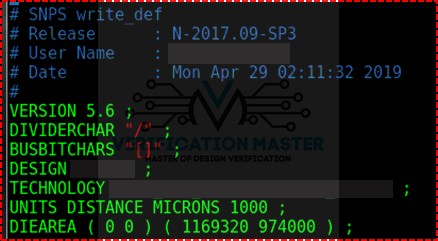
[VERSION statement];
           VERSION 5.7 ## DEF version
           [DIVIDERCHAR statement] ;
           DIVIDERCHAR “/”; ##Divider char representation
           [BUSBITCHARS statement] ;
           BUSBITCHARS[]“/” ##Bus, A bit of char representation
           [DESIGN statement];
           Design dummy design ;##Design  Name(Partition Name)
           [TECHNOLOGY statement]
           [UNITS statements] ;
           UNITS DISTANCE MICRONS 2000; ##unit definition
           [DIA AREA statement]

           [ROW statement]

           [Tracks statement]
           [CELL GRID statement]
           [VIAS statement]

           [NON DEFAULT RULES statement]
           [COMPONETS statement]
           [PINS section]
           [BLOCKAGE section]

           [FILLS section]
           [SPECIAL nets section]
           [NETS section]
           [SCANCHAIN section]
           [GROUPS section]
           [BEGIBNEXT section]
            END DESIGN statement
- Header Statement:
Below property definition of the core box(Boundary Box), where
-
- LL_X: Lower left of X Coordinate
- LL_Y: Lower left of Y Coordinate
- UR_X: Upper Right of X Coordinate
- UR_Y: Upper Right of Y Coordinate
- Row Statement
Example :
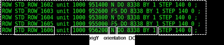
rowName: Specifies the row name for this row.
Sitename: Specify the LEF site to use for the row
origX origY: Specify the location of the first site of a row
site orientation:Specify the orientation of all sites in the row
example N= North
Do numX By numY:
- Specifies the repeating set of sites that create the row
- One of value must be 1
If numY is 1, then the row will be horizontal.
STEP stepX stepY :
It specifies the spacing between sites in horizontal and vertical.
GCell Grid statement
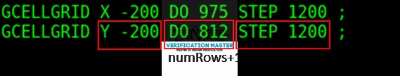
Description :
Start {X|Y}:
It specifies the location of the first vertical{X} and first horizontal {Y} track.
Do numColumns+1:
Do numRows+1:
It specifies the number of row or columns or row in the grid
Step space:
It specifies the spacing between the tracks.
Via Statement
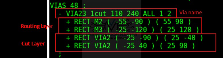
All vias consist of shapes on three-layer
- One cut layer
- Two routing (or master slice) layers connect through that cut layer.
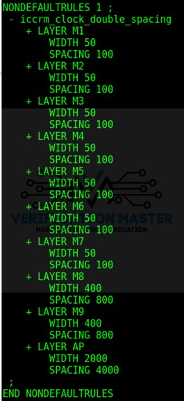
NDR statement:
In this, it defines any non-default rules used in the design that are not specified in the LEF file. This section can also contain the default rule and LEF non-default rule definitions for reference.
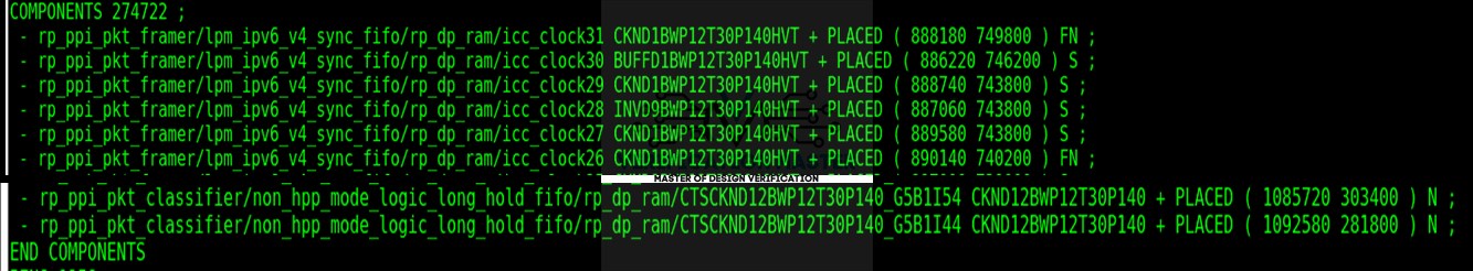
Component section
In this design component, their location and associated attributes are defined. Big section in DEF file.
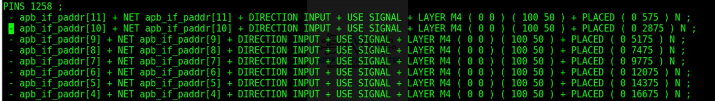
Pin section
In this, external pins are defined.
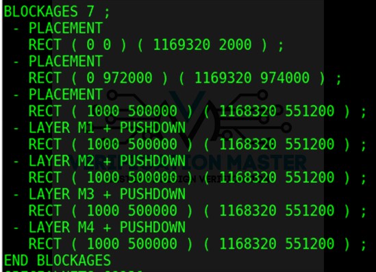
Blockage section
Placement and routing blockages in the design are defined.
PUSHDOWN: It specifies that the blockages were pushed down into the block from the top level of the design
Example.
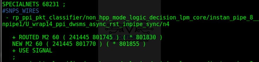
Special net section
Example
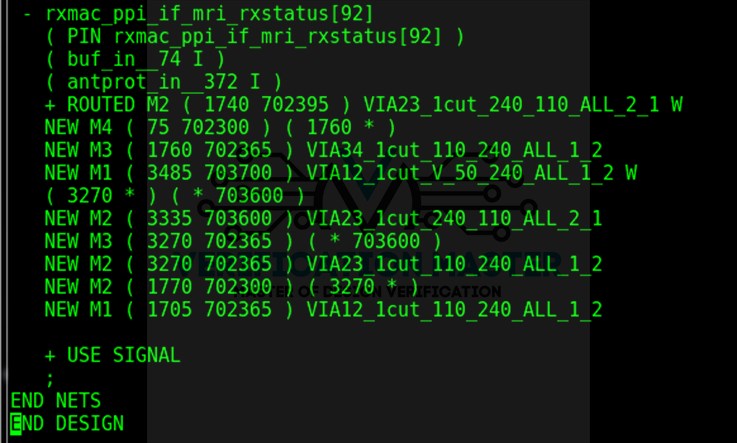
Net section:
Synopsys Design Constraints(SDC)
- Synopsys Design Constraints is a format used to specify the design intent including timing, power, and area constraints for the file
- This is the common format for constraining the design which supported by almost all synthesis, PNR, and other tools
- The file is saved in the .SDC extension
- In SDC, file syntax is based on TCL format.
- It can be generated by synthesis tool and same can be used for Place and route(PNR)
A few important constraints in SDC files are discussed below:
- SDC version
- Units
Design rule constraints
- Set maximum fanout
- Set maximum Transition
System Interface
- Set driving cells
- Set load
Timing Constraints
- Create clock
- Group path
- Create Generated Clock
- Clock uncertainty
- Clock latency
- Input Delay
- Output Delay
Timing Exception
- Multicycle Path
- False Path