Few Terms Related to the Floor plan
Core
It is defined as an inner block, where the fundamental logic like macros, standard cells is placed.
Die
A Die which consists of a core is a small semiconductor material specimen on which the fundamental circuit is fabricated.
Aspect Ratio
The aspect ratio defines the shape and size of the chip. It is the ratio between horizontal routing resources to vertical routing, or we can also say the ratio of height and width.
If the aspect ratio is 1 it means that height and width of the chip is the same. If aspect ratio is 0.5 it means width is 2 time of height (H=2W)
Aspect Ratio: Height(Horizontal Routing )
width (Vertical Routing)
Core Utilization
The area occupied by the macros, standard cells, blockage, and other cells is defined as utilization. If the core utilization is 70%(0.7) that means 70% of the core area is used for placing Marcos, standard cells, and other cells, and the remaining 30% is used for routing purposes.
Core utilization : Standard Cell Area + Macros Area
Total Core Area
Core to I/O clearance
Core to I/O clearances is the space from the core boundary to the inner side of I/O pads.

Concept of Row
In design, standard cells are placed in rows. All the rows have equal height and spacing between them. The width of the row can vary according to standard cell size. The rows get the power and ground connection from VDD and VSS rail.
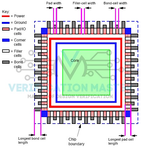
I/O Pads (Input Output pads)
- I/O pads are the pads that interact with an outside block of the chip to an internal block of the chip.
- I/O cells are placed in between the core and die at the floor plan stage.
- They are responsible for providing voltage to the cell in the core.
- Pads will have pins on all metal layers used in the design for easy access while routing the design.
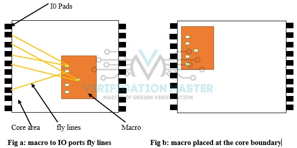
Fly lines
In-floor planning when placing a block on the chip manually, the layout tool shows lines between the pins of the block you are moving around the chip and other pins that are connected to other blocks. These are called fly lines.
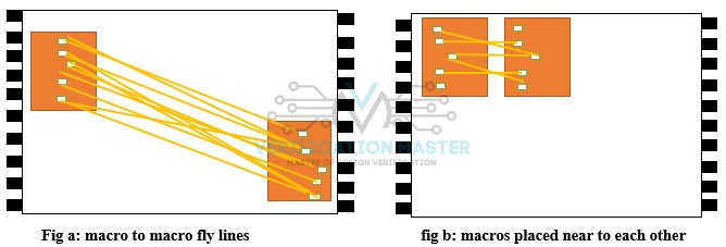
Let us take an example if we check net connections from macro to macro and macro to standard cells. If there is more connection from macro to macros, then place those macros near to each other and rather place them nearer to the core-periphery.
The main advantage to place block by fly lines connectivity is that it helps the designer to reduce routing resources
Fly lines are of two types:
- Macros to Macros fly lines
- Macros to I/O fly lines
Pitch
The distance between the center to center of the metal is called pitch.
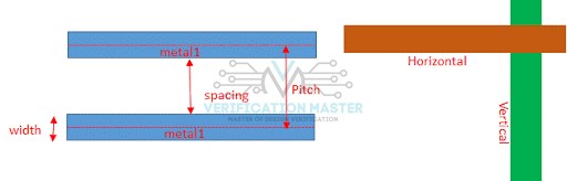 Fig. Pitch
Track
Track, generally used as a unit to define the height of the Standard cell.
Notch
The non-uniform shape formed due to taping is called notch. Notch areas are not utilized effectively. It will increase the placement density of the core will raise the congestion.
Corner Cell
Corner cells are simply dummy cell which have ground and power layer.
Bond Pad
A bonding pad is used to connect the circuit on a die to a pin on the packaged chip. In this, one side of the bonding pad is connected to gold wire while the other side is connected to the package.
Cell Orientation
Macros placement are done manually based on there connectivity with other macros and also with IO pad and Orientation of macros. In macros placement, we place macros according to fly lines. By using fly lines, the exact connectivity of macros to macros or I/O pads can be seen and with the help of these we can change the orientation of the cell.
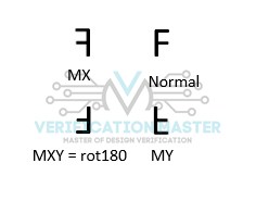 Different type of cell rotation
- Ro– No Rotation
- MX–Mirror through X axis
- MY–Mirror through Y axis
- R180–Rotate counter-clockwise 190 degrees
- MX90–Mirror through X axis and rotate counter-clockwise 90 degrees.
- MY90–Mirror through Y axis and rotate counter-clockwise 90 degrees.
- R270– Route counter-clockwise 270 degrees
- R90–Route counter-clockwise 90degrees
Core limited and Pad limited
Core limited
- In core limited, it has more logic and lesser I/O, which means core will decide the total area.
- More optimization is required.
Pad limited or I/O limited
- In pad limited, it has more I/O ports, which means inputs will decide the total area.
- We can’t care much for optimization here.
- It is easier to implement
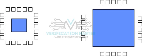
a) Pad limited b) Core Limited