Power planning is a step that is done with floor planning, in which a power grid network is created to distribute the power uniformly to each part of the chip.
Power planning means providing power to every macro, standard cell, and other cells that are present in the design. This creates power and ground structure for both the IO pad and core logic.
The width and spacing of power strips in each layer are decided depending on the power requirement of the device(Standard cell and complex macros). If more current needs to be flown through the device, a wider, stronger, power grid structure is needed.
Power planning is also called the pre-routed because in the chip power nets are routed first. In general, power routing is given higher priority overclock and signal to the route.
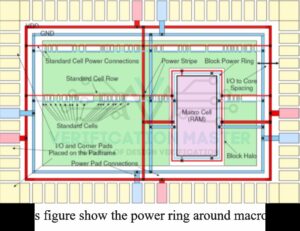
Fig1. Power planning
List of Input files for Power Planning tools:
- Netlist (.v)
- Synopsys Design Constraints(SDC)
- Database of floor plan
- Power Strap and Power ring width
- Tie cells information(VDD or VSS)
List of Output files from Power Planning tools:
- Power Routed database
- Power estimation Report
- Pre Route DRC checking report
Power planning involves calculating the number of power pins required, Number of rings, strips and IR Drop.
Power planning management is divided into two type.
Core cell power Management
One pair i.e. VDD and VSS power rings are formed around the core. If any macros/IP is power critical, then a separate power ring is created for particular macros/IP. According to power requirements, strips and trunks are created for macros.
I/O cell Power Management
Power rings are created from I/O cells. Trucks are constructed between the core ring and power pad