End Cap Cell(Boundary Cells)
End cap cells are added near the ends of the cell rows and around the edges of objects, such as the core area, hard macros, blockage area, voltage area, and corner cell.
End cap cells are placed just after macros placement in the floor plan flow. End cap cell has a fixed attribute, that’s why these cells cannot be moved during the optimization. End cap cells are needed in design because at the time of fabrication there are chances of getting damaged by the gate of standard cells placed at the boundary.
To prevent such damage, we add end cap cells which have a dummy poly gate. So if damage occurs at the boundary, only the dummy gate gets damaged and protects the actual gate of the standard cell.
End cap cells ensure that gaps do not occur between the N-well and implant layer and also prevent DRC.
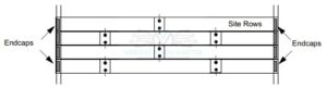
Fig1: End caps Cell
Tap cells
Well Tap cells(or tap cells) have no logical functions. They connect the n-well to VDD and p-substrate to VSS to prevent the latch-up issue.
After macro placement and creation of power rails, tap cells are placed. They are placed in a regular interval in each row of placement and the distance between the tap cells must be as per the DRC rule of that particular library.
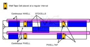
Fig2: Well Tap Cell
Spare Cells
Spare cells are used to modify or improve the functionality of a chip. They are extra cells and placed at regular intervals in the chip. They are not timing-critical.
When the design is tapped out and afterward there is a requirement to fix some bugs, then it is not possible to fix if we have not provided spare cells. This kind of floating cell is added in design so that after tape out if some bugs are needed to fix, we can make use of it.
There would be an insertion of approximately 5% spare cells in the whole design, not more than that.
Spare cells are connected to VDD/VSS when they are placed in the design and their output is left floating and if they are required to use their inputs are disconnected from VDD/VSS and connected to functional logic in Engineering Change order(ECO) mode.
Tie Cell
Tie cells are used to avoid direct connection of the gate to power and thereby protecting the cell from damage. Tie–high and Tie-low cells are used to connect the gate of the transistor to either power or ground. In tie high, one input gate is connected to VDD, another is connected to the signal net.
In tie low, one input gate is connected to VSS and another is connected to the signal net. These cells are part of the standard cell library.
De cap cells (Decoupling Capacitor cell)
De cap cells are temporary capacitors added in design between power and ground rails to counter function failures due to dynamic IR drop.
In a design, most of the power consumption is done by a clock circuit. Assume that all the clock blocks are switching simultaneously, a high current is drawn from the power grid for a small duration. If the power source is far away from the flip-flop, the chances are that the flop can go into a metastable state due to IR drop. To overcome these, de cap cells are added.
When there is a drop in the power rail, these cells act as a battery and maintain the voltage across the rail.