Pre-Placement
Before the process of placement getting started, few steps were performed here in this stage generally called as Pre-Placement Stage. In this stage following things are implemented:
Physical-Only Cells(Well Taps and Endcaps)
These cells present in the library which connect only to power and ground rails and do not have any signal connectivity.
Endcap Cells/Boundary Cells
Endcap cells do not have any timing model and contain only base layers.
High chances for the gate to get damaged for the cells placed near the boundary while chip manufacturing. To prevent such kind of damage these special kinds of cells in the stdcell library are placed at the boundary.
Where to place?
Endcap Cells/Boundary Cells, placed at both ends of placement row to terminate the row(left and right). Also placed at the top and bottom of the block(In block level) to make proper alignment with other blocks. These cells cannot be moved during optimization as they have a special kind of fixed attribute.
How to place?
End caps are placed before the stdcell placement and are therefore called pre-placed cells. Using a GUI interface or through tool commands, one can add these cells to the design.
icc2_shell>> set_boundary_cell_rules -left_boundary_cell saed32rvt_c/SHFILL3_RVT
-right_boundary_cell saed32rvt_c/SHFILL3_RVT

icc2_shell>> set_attribute [get_cells bound*] physical_status fix
saed32rvt_c/SHFILL3_RVT, saed32rvt_c/SHFILL3_RVT are cell names. Will wary from design to design.

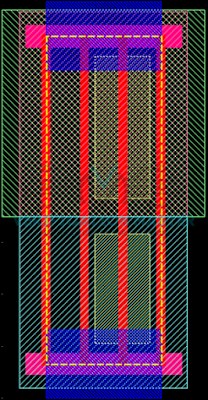
Layout of Endcap Cell

Endcap Cells
Well Tap Cells
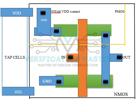
Well-tap cells (or Tap cells) are used to prevent the latch-up issue in the CMOS design. To prevent the latch-up issue these cells connect the nwell to VDD and p-substrate to VSS. No logical function is present in a well-tap cell rather than providing a taping to n-well and p-substrate therefore well-tap cell is called a physical-only cell.
Well-Taps have only two connections:
- nwell to VDD
- p-substrate to VSS.
Why Tap Cells?
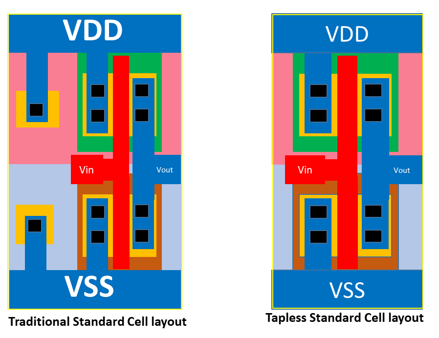
Earlier Standard cells were designed in such a way that each standard cell had nwell connected to VDD and p-substrate to VSS connection within the standard cell and this structure does not need any well-taps in design. But this kind of standard cell design had consumed more area and to save the area, a concept of Tapless cell has been introduced. In a tapless cell, there is no well-taping inside the standard cell, well taping is provided by a separate standard cell which is called a well-tap cell. So well tap cell is a part of a tapless standard cell library.

Well Tap Cell

TapCell Layout
Tap Cells are used to prevent Latchup in the design.
To create Tap Cell and fix them
icc2_shell>> create_tap_cells -lib_cell saed32rvt_c/SHFILL_RVT -distance 30 -skip_fixed_cells

icc2_shell>> set_attribute [get_cells tap*] physical_status fix
Check if Taps and endcaps are placed properly with no violation
icc2_shell>> check_legality -cells [get_cells bound*]

icc2_shell>> check_legality -cells [get_cells tap*]
Special Cells(Spare Cells and Decap Cells)
Spare Cells
Spare Cells are extra cells placed in layout for future ECO(when a bug is found in design during tape-out and Silicon is sent back). Now using Spare Cells logic conversion can be done instead of regenerating layer mask. These cells are not timing critical and PnR Tool will place them all together when constraints are not specified. However, as one does not know the exact location of using Spare cells it’s better to sprinkle them on a layout. Spare Cells can be any logic cells.
Ex: AND, OR, MUX, De-MUX etc.
Inserting Spare cells
- Before placement
- The designer adds a separate module with required cells and starts PnR with spare cells included, taking care that the tool hasn’t optimized them away. There can be more than one spare module.
- Spare cell inputs are tied to GND/Power nets and output’s left unconnected( floating nets shouldn’t be designed as they give a logic error).
- During Placement
Use command to provide PnR to add spare cells to netlist in the placement stage.
insert_spare_cells -lib_cell { cell_name}
Decap Cells
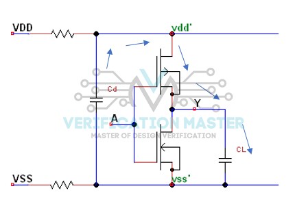
Decap Cells are added in the design to encounter functional failure due to dynamic IR drop. If a power source is far away from a flop, the chances that the flop may not receive the required power for switching functionality due to IR drop. To overcome this decaps are used.
Decaps can also be used as fillers but an increase in usage can increase leakage current. So, use effectively.

Decap Cell
At the active edge of a clock when a current requirement is high, these decaps discharge and provide a boost to power grids. It’s a capacitor that goes between Vdd and Gnd in parallel with the rest of the logic gates. When logic gates draw current this capacitor provides extra charge close to that current. When logic gates are not drawing current, the capacitor charges up to maximum capacity and sits there waiting to be discharged.
At last, create Placement Blockages to avoid routing congestion.
Pre-Placement Optimization
Remove delay models, if present.
As there is no timing/clock in the design, no use in having delay models. If any delay models are present in the design(like an existing built clock tree when a design is back to placement stage in the next iteration after CTS is performed), better remove the existing delays and perform pre-placement.
Zero RC Optimization
Considering only Cell delays but not Net Delays (Since there is no actual routing in the design). Here pre-placement has no physical routing but only logical connectivity of cells is present. So as every specific body (cell) has some kind of resistance within them, only cell delays are calculated but not net delays are taken into consideration.
Take care of don’t use cells while optimizing
What are don’t use cells?
“Don’t use cells” are those cells which are present in the Library and you don’t want to use those cells in your design.

