All wire load models are removed before the start of placement optimization. Placement uses R and C values from the virtual route for timing calculations. The virtual route is the Manhattan distance between two pins. Virtual route RC values are more accurate than Wire Load Model RC values.
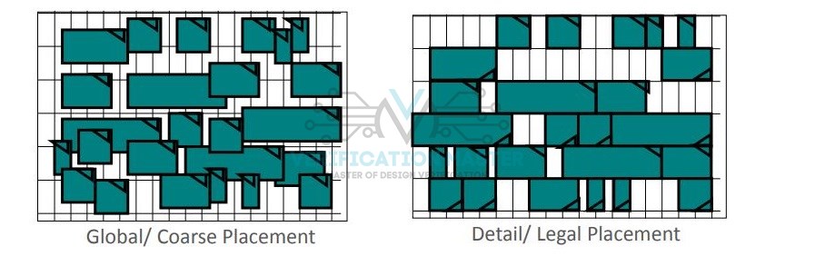
Global/Coarse Placement
During this phase, the PnR tool will determine the approximate location for each cell according to timing and congestion. Macros here act as placement blockages for standard cells. Coarse placement is performed for initial timing and congestion analysis.
Detail/Legal Placement
During legalization, the tool will move cells to a legal location for avoiding overlap between cells. These changes in cell location will change the length of nets/wires leading to new timing violations. These can be fixed by incremental Optimization.
 Scan Chain Re-Ordering
 Scan Chain Re-Ordering
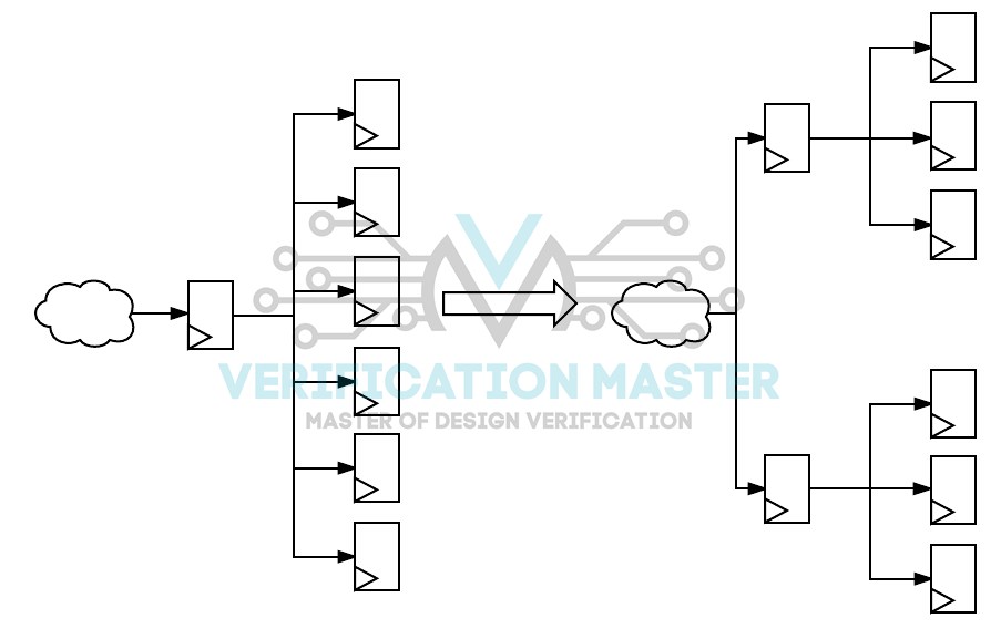
It is the process of reconnecting scan chains to optimize for routing by re-ordering the scan chains which improves congestion as well as timing. At the time of placement, the optimization may take the scan chain difficult to route due to congestion. Hence the tool re-order the chain to reduce congestion. Since logic arbitrarily connects the scan chain, It is better to reorder after placement so that, scan chain routing will be optimized.
High Fan-Out Net Synthesis(HFNS)
High Fan out the net is the net that drives more loads. There is a limit for a maximum number of loads per net. The nets which cross more than these limits are known as high fanout nets. The process of buffering the high fanout nets is known as High Fanout Net Synthesis.
Clock nets, Scan, Enable, Reset nets are generally high fanout nets. HFNS is performed at the placement stage. Since clock nets are considered ideal HFNS is not performed on them. Also on don’t touch attributes HFNS is not performed.
set_max_fanout 20 [design_name]
HFNS
Global Route
After having the exact location of Standard Cells in design, the whole floorplan area is divided into an array of rectangular sub-regions each of which has n number of routing tracks in each dimension called Global Cells/Global Route Cells(G-Cells). This is performed to identify the Routing congestion Map and internal parasitics.
What is Virtual Route?
No information is available regarding the placement of the cells before or at the stage of the floorplan. Based on the knowledge of netlist which gives the fan-out information of the driving cells, early prediction of the route length is done. These routes are known to be Virtual Routes.
Optimization Techniques (Pre-CTS Opt)
Construction of netlist only changes existing gates, does not change functionality.
- Buffering
- Swap of pins that can change final delay
- VT Swapping
- Cell Sizing
- Cloning
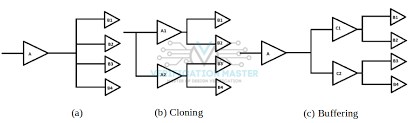
- Buffering
To drive a load that is too large for a logic cell to drive(exceeding fanout value) buffers are inserted in design. The long net is broken and buffers are inserted. This will improve Setup Violation by improving the timing(transition) on the data path. Buffers can also be inserted to add delay on data paths which simultaneously improve Hold Violation.
To make the violated path a little slow to meet the timing, a buffer(a kind of delay) is added in the clock path of the capture flip-flop. This added delay makes the path slow down the signal transition eventually clearing the Hold Violation.
- Pin Swapping
This Optimization will examine the slacks on the inputs of the gates on the worst timing paths and optimizes the timing by swapping nets attached to the input pins, so without changing the function of the logic the net with the least amount of slack is put on the fastest path through the gate.
- VT Swapping
LVT, SVT/RVT, HVT(Lower Vt, Standard/Regular Vt, High Vt) can be swapped according to requirement.
Speed: LVT>RVT>HVT
Leakage: LVT>RVT>HVT
Though LVT’s are faster than the rest, do not add more of them in design as they are leakier.
So, better give priority to RVT first.
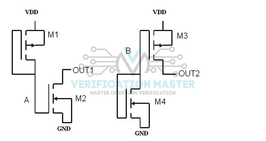
- Cell Sizing
This is a process of assigning a drive strength for a cell in the library. When there is a lower drive strength cell that is timing critical then this particular cell is replaced by a higher drive strength cell to reduce the timing violation(majorly Setup).
When a low drive strength cell, say 2x is made to 4x or 8x which is of higher drive strength, the cell delay depends on two components namely input transition and output load, this increase in load value from 2x to 4x/8x makes the signal transition fast as delay is reduced with improved drive strength. Setup violates when the data path is slow. Now, this improved drive strength will eventually improve the Setup.
- Cloning
Cell cloning is a method of replicating the cell to decrease the load of a very heavily loaded cell. By connecting an identical cell to the same inputs as the original cell this replication can be achieved. Cloning/Replication is done to improve timing.
TIE Cell insertion
Some unused inputs are tied to VDD/VSS (logic1/logic0). Connecting a gate directly to the power network is not recommended so, we use TIE1 or TIE0 cells if available in the library. These single pin cells effectively tie the pin it connects high(1) or low(0).
TIE High(1) and TIE Low(0) cells are used to avoid the gate connection to the power/GND network. There will be a case, where the gate is damaged due to power/gnd bounces. So these circuits are used to protect the gate from such damage.
set_attribute [get_lib_cells */TIE*] dont_touch false
TIE CELLS